Artificial Intelligence
Computer Vision AI: The Key to Unlocking Sports Analytics
Recent developments in our ability to understand posture from an image or actions from a video have opened avenues to analyze and get insights for recreational activities with limited human intervention. This technology, popularly known as Computer Vision, is majorly supported by Machine Learning based Neural network models that can detect different objects, human body poses or even body parts.
Insights
- The world of sports is constantly evolving, and this ability by Vision AI models has helped in creating applications for real-time gaming without using sensors or equipment mounted on the subject. It also has multiple applications in sports. shopping and other areas of our day-to-day life.
- This paper focuses on the technical aspects of player serve analytics using Vision-based AI models to detect Body Skeleton Pose details along with Object Detection / Segmentation tasks.
- The solution details and provides prescriptive guidelines to handle challenges that serve as a base for action-based analytics (e.g. Sports / Gaming). This paper also discusses on the physical real-world setup and architectural aspects of delivering similar computer vision-based projects.
The main objective of the ‘Serve Analysis’ were to engage & connect with tennis fans in a unique and impressive manner by creating an experience that they could cherish and share with their friends & family. The high-level objectives defined were to show them as if they are serving in the main court and provide insights on their serve, thus helping them to understand and improve their serve.
Key objectives of the project were:
- Identification of right or left-handed serve
- Identification of Ball Toss and Ball Hit poses
- Pose analytics for Ball Toss and Ball Hit poses
- Analysis of serve whip action
- Analysis of sweet spot hit on racket
The Serve Space setup
The Serve Space requires specific setup for Computer Vision to help with required information. Key specifications to be kept in mind for area setup are detailed in Figure 2.
Camera specification is another important aspect for analytics. Table 1 lists key camera specifications.
It is recommended to decide these settings upfront based on output and few trial runs. Videos created using these settings should be used to train / tune Computer Vision models. This will ensure models are trained on the right dataset to give consistent outcomes in production.
Figure 1. How image brightness changes with shutter speed
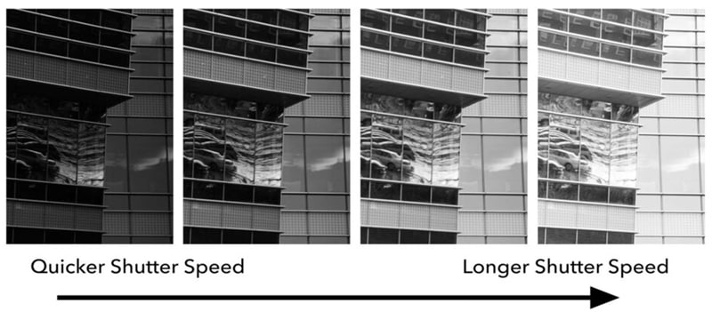
Figure 2. Illustration of ‘Serving Space’ Setup
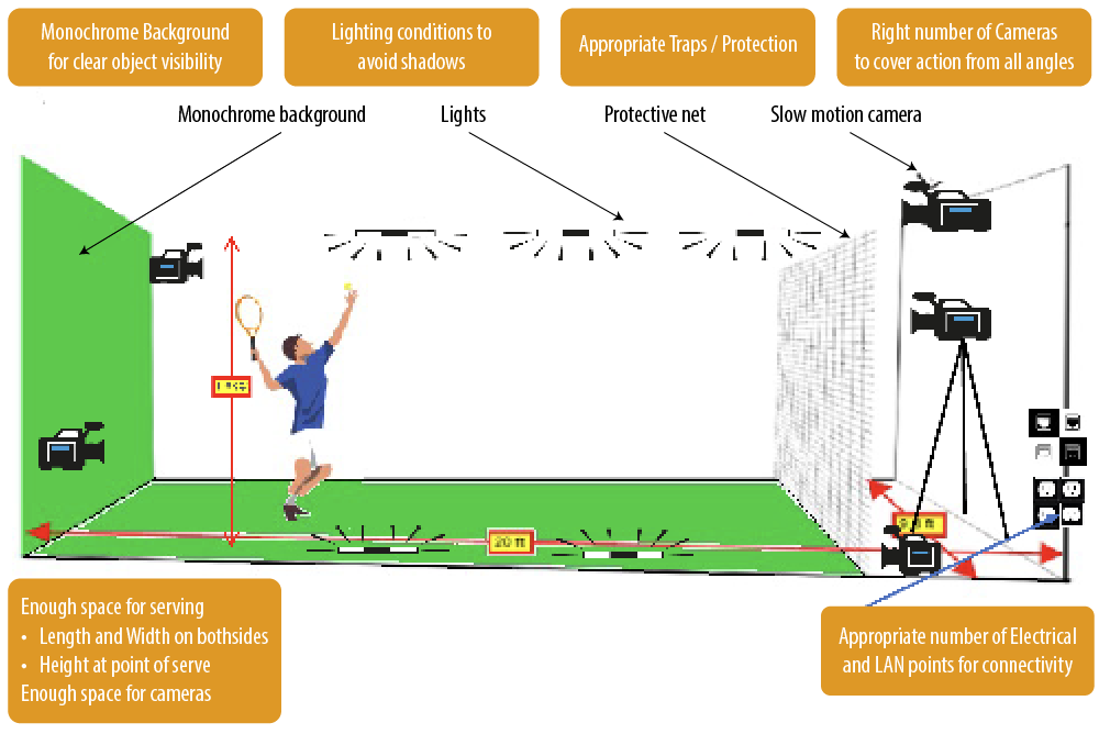
Table 1. Camera Setup Specs
| Parameter | Specs | Value used | Reason |
|---|---|---|---|
| Shutter Speed |
|
1/250 - Changing during day | Remove haziness of moving objects for better detection |
| FPS |
|
60 FPS | Video clarity Processing time |
| Resolution |
|
Full HD | Better object clarity |
| Bitrate |
|
35 Mbps | For clarity of object and image |
Computer Vision AI techniques for understanding action
The following sections break down the problem into smaller steps and describe techniques and approach taken to address each of those steps. The small size of the Arena permitted placing only 1 frontal camera, as well as relying on natural changing light that posed specific challenges. Key challenges to be addressed can be summarized as below:
- Capturing fast motion action with clarity on each of the moving objects
- Visibility of objects of interest during all important actions
- Ability to get 3rd dimension (depth) information for understanding action
- Handling fluctuating light conditions throughout the day
- Fast response time for high FPS / high quality videos
- Varied data covering different scenarios & conditions
Pose / Action identification
Figure 3. Ball Toss Pose
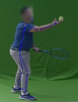
Figure 4. Ball Hit Pose
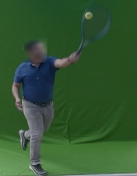
Pose or Action identification is to find exact frame of the video when a particular action happened, e.g., Ball Toss or Ball Hit. Only a small number of frames can be identified to capture this action. Computer Vision and Data Science based techniques need to be deployed to identify the exact frames.
The options considered were whether to go with a Heuristics-based approach or use Deep Learning-based image classification techniques. Heuristics-based approach is where data for few different serves is analyzed to determine image features and a solution is approximated based on knowledge of problem domain, which in this case was to find the right pose or action. E.g., The ‘y’ position of the wrist is always within a certain range of the ‘y’ position of the shoulder during Ball Toss. This is one of the features that can be used for Ball Toss identification. In an image classification approach, model is trained to extract & understand image features by itself.
Figure 5. Ball Toss Pose Identification checks
Check ball when it starts moving up from hand (y axis)
Current frame distance (Ball wrist y to Ball y) > Previous frame distance (Ball wrist y to Ball y)
Check if Ball is still in hand even on x axis
Distance (Ball wrist x to Ball x) < Ball x distance threshold
Check if Wrist is between certain distance (y) of Shoulder
(Ball Shoulder y – Minimum Threshold) < Ball Wrist y < (Ball Shoulder y + Maximum Threshold)
Figure 6. Ball Hit Pose Identification checks
Check if this frame is Minimum x frames after Ball Toss
Current Frame Number > Ball Toss Frame + Frame Difference Threshold
Get frame with minimum Ball and Racket distance
Distance (Racket to Ball) < Minimum Distance till Now
Store if true and set Minimum Distance accordingly
Racket should be above Serve Shoulder
Distance (Racket y to Shoulder y) > Difference Threshold
Image classification technique requires lot of data under different scenarios for model to learn and understand the nuances. In addition, the actual features learnt & used for classification would be internal to the model and might not be easily explainable, limiting the ability to debug and fix any specific scenarios quickly. On the other hand, the Heuristics-based approach, can work with limited videos (though some nuances might be missed if those scenarios are not captured). It also enables the model to explain nuances of the solution and thus helps to debug & fix quickly when a new scenario is encountered. This needs appropriate Data science analytics. Due to limited data availability, changing arena conditions and priority to have a clear explanation of each of the decisions for ability to debug and modify for a new scenario, Heuristics-based approach was selected.
Heuristics based approach helps understand the overall logic and to explain the outcome. It is also easier to debug and fix it by looking at the serve video where logic is not working.
However, to be able to analyze the data, the required base data from the video was needed. The main objects of interest in our image were the person serving, the racket and the ball.
Object Detection and Segmentation
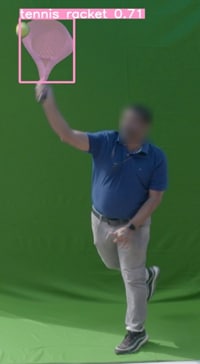
For the Racket and the Ball, the information available in each video frame are their positions and the outline. Various other models like Detectron2 and Yolo* family of models were tried out. We even looked at an option to fine tune models by using blurry images of objects, however this had to be dropped due to insufficient availability of data. For fast moving objects like Ball and Racket in a tennis serve scenario, where objects were blurred out in the frames, Yolo models were giving better results. Thus, Object detection model of Yolo was used for detecting these objects and Yolo-seg model was used to find out segmentation mask of objects. Feature of passing full image in inferencing pipeline was used to improve results further.
Data from these models like bounding box positions and mask details of objects were used to find required features like ball center, racket net center, racket tip for pose identification as well as to improve scoring aspects. This will be covered in more detail in later sections.
Figure 7. Object Segmentation
Body Pose Detection
Detailed information about the player is required in order to determine posture as well as other information for analytics. Position of different body parts & joints of the player is needed to determine the actual pose. With recent body pose models, key points of the player’s body such as wrist, elbow, hip etc. can be identified. Options considered were Detectron2, Yolo* and Mediapipe for body pose detection. The set of criteria decided for selecting the right model were:
- Available number of keypoints
- Availability of 3D coordinates
- Accuracy
- Licensing considerations
- Infra needs
- Inference speed
Detectron2 only gave 17 keypoints and no 3D coordinates so it was rejected. Except for accuracy which was almost same across Yolo-pose and Mediapipe, Mediapipe was better than Yolo-pose and hence selected. Yolo gave 17 keypoints while Mediapipe was able to produce 33 keypoints. Mediapipe was also able to give an approximation of the 3rd dimension as an added data point in a single camera view. These inputs were useful to come up with a more stable solution for pose information, hence Mediapipe pose model was selected.
Figure 8. Mediapipe Keypoints
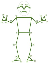
Source: Pose landmark detection guide | MediaPipe | Google for Developers
Model comparison by Features
| Features / Model Name | Mediapipe | Yolo | Detectron2 |
|---|---|---|---|
| No. of Keypoints | 33 | 17 | 17 |
| 3D Coordinates | Yes | No | No |
| Can handle more than 1 person | No | Yes | NA |
Figure 9. Body Angle and Distances
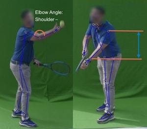
Using the keypoints position, racket, and ball positions as well as ball & racket center and tip, various other features were determined such as body orientation of server, body joint angles, distance between various body parts and body parts to objects. This data was further used to find out the serve hand, ball movement direction, racket movement direction and ball / racket speed.
Serve Hand detection (Left vs Right)
Serve Hand detection is about identifying whether serve is being done with left or right hand. Detection of Serve hand is an important aspect required to determine other information such as which hand is holding the racket v/s which hand is holding the ball. This information is further useful to determine the pose as well as scoring for various poses and serve aspects.
There are multiple options that can be used to determine Serve Hand detection using Computer Vision aspects.
One of the options was to check variance in distance between wrists and the ball / racket that will help determine the wrist holding the racket / ball and thus determine the serve hand. It is suggested to use the wrist and ball distance rather than wrist and racket distance to determine the non-serve hand as racket size will keep changing and affect distance from the racket center, causing issues with determination. We wanted to determine serve hand from initial few frames, and we found issues since some people have a way of holding both hands before tossing the ball.
The other option is to check body orientation of the server from the serving line which is parallel to the camera. Body orientation is the angle of the server’s body from the serving line. Orientation can be determined based on the angle between the z axis and the serving line (x axis) formed by server’s legs, hips, or shoulder, and this can help to identify the serve hand. In case of single camera, a 3D model is required to understand the depth (z axis) and hence it is not used.
Figure 10. Body Orientation
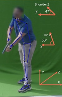
Figure 11. Left-Handed vs Right-Handed Serve
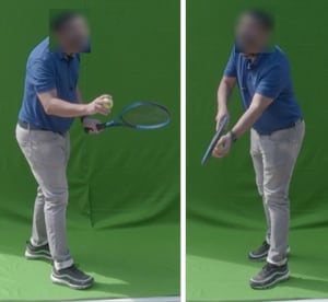
The other option is to determine the side of the body to which the person is holding the racket as it was producing good results on different videos being processed. Check if racket is held on right or left side of player from camera perspective to decide serve hand. Using a median of the initial few frames is suggested to ensure some frames do not result in decision bias.
Another option is to use Classification based on training a model to determine serve hand. Train a model with images and features to determine serve hand. This requires a large dataset, but the machine can comprehend actual features and the weightage in this case. However, this approach lacks explainability in many cases.
It is recommended to use a combination of the techniques suggested to avoid bias and cover multiple scenarios if good dataset is not available for training. However, if available, it should be possible to get all different features and train a model as well.
Sweet Spot Analysis
The position where the ball hits determine the vibrations as well as speed of ball travel and is important for a good serve. This analysis is to identify the spot on the racket net where the ball hits.
For finding sweet spot position, first find the racket center and racket ellipse covering edges of the racket. Since racket is shaped like an ellipse, concentric ellipses were used to calculate how far the ball is from the racket center. Score of 0.0 to 1.0 (100 concentric ellipses were used to determine this score) is determined based on the distance of the ball from racket center.
Figure 12. Ellipse fitting to Racket
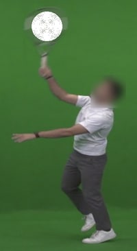
Figure 13. Sweet Spot Identification
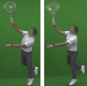
To identify the Center of the Racket and the ellipse covering the racket, Options are either using bounding box coordinates to determine racket center, using a line to divide the tennis racket mask into equal parts to determine center line, or fitting an ellipse to the racket that will help determine racket alignment and thus the net position.
Figure 14. Sweet Spot Logic
The bounding box coordinates did not work when the racket was in different positions. Dividing the racket into 2 equal parts also failed since sometimes the division did not split the racket from tip to racket handle in 2 parts but other ways as well. The ellipse method was handled using OpenCV ellipse fitment function to the racket mask, which helped to understand racket orientation and based on that it was able to determine center line of the racket. This further helped determine racket net center as well as racket tip. Based on the use case, the method may vary, however the approach must be around determining the object shape.
Whipping action analysis
Whipping action determines the force created by the player to be passed on to the ball during hit. This is an important factor for a fast serve. Angle of racket movement combined with movement speed was used to determine whipping action.
Figure 15. Racket Ellipse fitting
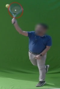
Figure 16. Whipping action Racket movement between 2 frames
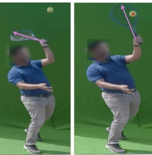
Due to limitations of having single camera, getting exact speed and angle was not possible, however it was possible to find out the difference in various serves from the same angle. These approximations were then used to determine the corresponding level of whipping action.
The distance travelled by racket tip in pixels helped to differentiate serve speeds in a fixed FPS scenario. It was confirmed that serve will always be from the same location and towards the camera. It is suggested to use multiple cameras in such cases to be able to get details from multiple angles.
To handle error in distance calculation due to single camera constraint, angle of racket movement between these frames was also calculated to determine whipping level as given Figure 17 and 18. Weighted average of distance and angle scores was then used after normalization.
Figure 17. Logic to calculate racket travel distance
Figure 18. Logic to calculate racket travel angle
Racket travel angle = Angle (slope of line in frame x, slope of line in frame x-t)
* Line is the line from Wrist to Racket tip in that frame
* x = Frame number of ball hit
Serve hand wrist point and racket tip was required to be able to determine the information required here.
To determine racket tip, the same ellipse fitting method was used to determine racket alignment and then the line from wrist to ellipse center that intercepts the last point on the racket mask . There were several other options such as using top line center of racket bounding box or some other mechanism like identifying serve hand wrist position and then using bounding box coordinates to undermine where the tip might be. Racket tip identification in case of tilted racket (instead of straight up) could not be correctly determined using other methods and the racket ellipse method fitted the scenario well.
Functionality to Steps and Model mapping
Table 3. Overall Functionality to Steps and Model mapping
| Functionality | Steps | Model used |
|---|---|---|
| Body pose detection |
|
|
| Serve hand detection |
|
|
| Sweet spot analysis |
|
|
| Whipping action analysis |
|
|
Solution Overview
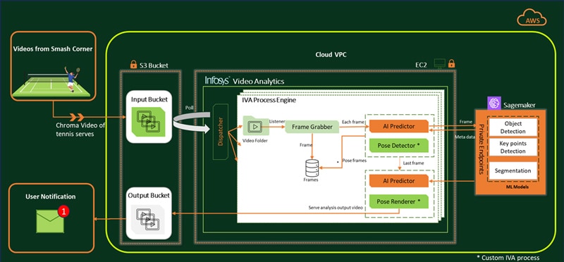
In this solution, Infosys Video Analytics, part of Infosys Topaz acts as the core video processing engine for pose classification and it is deployed on Amazon Web Services (AWS) cloud. IVA’s key modules, Frame Grabber and AI Predictor, are leveraged, and custom business processes are developed to handle player pose classification function. Any inferenced metadata generated by the models are kept in memory for faster retrieval and real-time analysis.
Key IVA modules used for Video Processing:
Frame Grabber grabs the frame as per frame interval, image resize configurations and requires frame pre-processing.
AI predictor is enabled to inference locally placed models as well as AWS Sagemaker hosted models.
IVA custom processes are developed to meet use case requirements. IVA inferencing flow is customized using router module to hook in custom processes.
Let us go through the overall flow of video processing which gets triggered once it is published by the on-ground operator from main Arena:
Dispatcher distributes input video files from S3 into IVA process folders. As soon as video is placed, IVA frame grabber starts grabbing frames of the given input video. For each frame, it then calls AI Predictor to invoke Object detection and Pose estimation models. The call is then routed to a custom Pose Classification process to analyze, determine the pose and associated pose frames. For the last frame, AI predictor triggers a segmentation function to get accurate racket details. At the end, relevant pose images & videos are generated which is then uploaded into target storage i.e., AWS S3 bucket. On successful processing, IVA process becomes available to process the next video.
Infosys Video Analytics, part of Infosys Topaz – The Smart Way to Leverage Video Content
Figure 20. Infosys Video Analytics, part of Infosys Topaz Solution Overview

Infosys Video Analytics, part of Infosys Topaz is an AI-based solution that empowers businesses to leverage video content for actionable business insights. Packed with rich features to deliver vision-based use cases, it helps enterprises identify scenarios, actions, objects and much more within videos. The solution ingests feeds from motion, fixed cameras and different vision-based sensors. Simultaneously, it also scans each frame of the video, extracts information about events in the frame, and saves this as metadata in a selected database. The solution architecture comprises many layers such as data persistence, data processing and APIs for analytics. Other capabilities such as data mining, knowledge curation, and service curation are also available and can be customized to Enterprise use case need.
Key Learnings and Prescriptive Guidelines
We faced several challenges as described above and have figured out various ways to overcome them. We have detailed the same below and that can be used for the various aspects of Computer Vision related sports and related use cases.
- Fast motion action: Fast moving objects are too hazy in videos and their position between two frames is quite far from each other to determine certain analytics
- High shutter speed helps reduce haziness of fast moving objects
- Higher FPS should be used to avoid the object from changing position too much between frames
- High resolution camera is required to help with higher number of pixels for better object identification
- Camera angles: Multiple cameras are required to cover all angles and synchronization between cameras can be challenging
- Need to plan at least 2 cameras to cover front or back and side angles
- More cameras will help cover different angles
- 3 cameras are optimum, considering cost vs coverage aspects
- Camera position will depend on overall area, serve hand and other aspects
- Area should be long and wide enough to have multiple cameras cover it from different sides (We did not have that privilege due to client setup restrictions)
- Need to take care of camera synchronization to ensure frame-to-frame mapping between multiple cameras
- Occlusion: Certain body parts or objects can be occluded or go out of camera angle so it would not be able to identify them
- Multiple cameras can help in avoiding this issue
- Can use object tracking options for position approximation
- Can use a different nearby frame for identification and consideration
- Depth related information is difficult with standard camera: In case of a single camera, the z axis information is not easily available with standard camera thus causing issues when calculating angle and distance
- Multiple cameras can help in avoiding this issue
- In case multiple cameras is not an option due to size, a LiDAR Depth camera can also be considered
- Another not so accurate option can be using a model like Mediapipe having some depth estimation or training own model for the same
- Lighting changes: Due to shadows and parts of body being highly illuminated, identification of objects and certain body parts becomes difficult
- Ensure proper lighting and diffusers to avoid getting shadows for better results
- Camera shutter speed and other parameters can be tuned based on light during that part of the day
- Choose right models / datasets to be able handle shadows / body parts
- Test with videos taken during different parts of the day and night to avoid any surprises later
- Slow response time: Due to high FPS videos and high-resolution images required for detection, model response time is low
- Plan for good hardware to ensure faster turnaround time
- Enable parallel / async processing to provide faster turnaround time
- Use sampling, if possible, to reduce number of frames getting processed
- Use image resizing for faster image inferencing and processing
- Negotiate enough time for giving back response upfront to avoid issues later
- Availability of varied training and test data: It is difficult to get training and test data from specific angle and distance required, posing challenge with Machine learning training and also testing of the outputs
- Use pre-trained models as much as possible
- Explore datasets online from different sources
- Ask upfront for data from source
- Have a team for annotating data received from different sources
Conclusion
Recent advancements in AI and specifically Computer Vision have enabled us with the ability to get insights from images and videos. This can help augment humans working in various domains such as sports, factories, retail shopping floors and many more. AI can help handle hazardous environments or terrain, tedious & standard tasks as well as removing physical challenges and human bias. This can enable humans to focus on tasks that are more decision oriented as well as intellectual.
Computer Vision techniques can enhance sports analytics and training. Some of the use cases where this can help tremendously are Experience Zones for sports enthusiasts, match analytics, training for amateur / professional players, strategy planning by understanding opponent’s game, self-capabilities & limitations, body posture analytics to help long-term health and ergonomics for players. The opportunities are endless, and this is just the beginning of a whole new dimension.
References
- Pose landmark detection guide | Mediapipe | Google for Developers – Mediapipe keypoints image
- Understanding Shutter Speed for Beginners - Photography Basics (photographylife.com) – Camera Shutter speed output explanation
- The Future of Sports: Infosys CMO Sumit Virmani On The New Emerging Technologies That Are Disrupting The World Of Sports | by Authority Magazine Editorial Staff | Authority Magazine | Jul, 2023 | Medium – Document from the RG experience

Subscribe
To keep yourself updated on the latest technology and industry trends subscribe to the Infosys Knowledge Institute's publications
Count me in!


